
How to Charge A\C Units
Procedures for Recharging Air Conditioning Systems with Refrigerant
Refrigerant charging might be the least understood practice in the air conditioning industry next to setting airflow. Although there are several methods, typically there is only one correct method for the type of unit you are working on. Information contained here is for formally trained EPA Section 608 certified technicians.
Start with the basics for all systems:
- Makes sure the system been properly installed and evacuated. A proper evacuation is critical to proper performance. Need help with this process go HERE!
- Clean the filters and the coils. You cannot charge or check the charge on a system with dirty coils, filters, or blower. The condenser and the evaporator must be clean. The blower must be capable of moving the correct amount of air. Visual inspection of the evaporator can be aided with the use of a video scope by removing the high limit of most furnaces and fishing the shaft up through the heat exchanger to the bottom side of the coil.
- Set the required airflow. You cannot charge a system without correct airflow. After the system is confirmed clean, the airflow must be set to the manufactures recommended settings. Typically this is 400 CFM/Ton +/- 10% Need additional help with airflow go HERE!
- Identify the type of metering device. You need to know what type of metering device the system has as this may determine how the system will be charged. (See photo below.)
- Before installing your gauges, vent the hoses and the manifold with virgin refrigerant (The same type as the system.) to avoid the introduction of air into the system.
- Blends like R410a or 404a must be added to a system as a liquid. Pure refrigerants like R22 can be added in liquid or vapor states. If adding liquid into the suction like, throttle it in slowly to avoid slugging the compressor or diluting and washing out the compressor oil.
- After the charge has been set, avoid installing the gauges as part of regular service. The system should be sealed. Keep it that way!
Methods that can be used to properly charge a system include:
1. Total Superheat Method (Fixed Orifice / Piston / Capillary Tube / Non-TXV)
Temperature must be above 55°F outdoors and above 70°F indoors with a indoor wet-bulb temperature above 50°F The evaporator coil cannot operate below freezing or an overcharge and possible compressor damage could result.
When a system is equipped with a fixed metering device or capillary tubes, the total superheat varies with the outdoor air temperature and the heat load on the evaporator (air temperature and humidity). When properly charged the total superheat will be within 3ºF of the target superheat for the current load conditions. Overcharging and undercharging both have a considerable impact on efficiency and humidity removal so the correct charge is critical to proper operation and creature comfort.
The total superheat method is the most accurate method of charging fixed orifice or capillary tube systems. These systems are critically charged and require correct airflow and accurate test instruments to properly and accurately charge the system. An R410a and R22 charging calculator or the "Non TXV Charging Guide" are required to determine the target total superheat. Because these systems do not "control superheat" it is critical that the airflow be as close to possible to correct prior to charging as the system will be charged to the airflow. The total heat in the air will be the driving factor for the evaporator performance so low or high airflow will have a direct impact on the charge and the system performance.
- If not already in operation, assure that the system is leak free and a proper evacuation has been performed to assure proper degassing and dehydration of the piping and the evaporator coil.
- Verify clean coils and correct airflow prior to charging.
- Attach a high accuracy digital gauge like the iManifold, Testos, or Fieldpiece SMANs to the service ports. Make sure the gauge has been zeroed, if required barometric pressure offset adjusted to current conditions, and the proper refrigerant type selected. Follow the gauge instructions.
- Attach temperature probes to their proper locations on the suction and liquid lines assuring good contact to the line with the sensor at the 4-10 O-clock position, at least 6" from the compressor and attached to a horizontal section of line (suction only). Typically installing the sensor on a straight section of line near the service valves is perfect.
- Measure the return air wet-bulb in the duct just before the coil, and outdoor dry-bulb conditions with a digital psychrometer.
- Determine the target superheat from the charging calculators or Table RD-2 on pages RD7 and RD8 of the "NON TXV Charging Guide" (See example below, 95°F ODA and 67°F indoor wet-bulb, target superheat 12ºF.)
- ADD refrigerant to DECREASE total superheat.
- REMOVE refrigerant to INCREASE total superheat.
- Allow approximately 10 to 15 minutes of operation after refrigerant has been added or removed to determine final superheat.
- Verify proper evaporator performance (temperature split) using page RD9 of the "NON TXV Charging Guide".
2. Condenser Subcooling Method (TXV)
Temperature must be above 60°F outdoors and above 70°F indoors with a indoor wet-bulb temperature above 50°F The evaporator coil cannot operate below freezing or an overcharge and possible compressor damage result.
- If not already in operation, assure that the system is leak free and a proper evacuation has been performed to assure proper degassing and dehydration of the piping and the evaporator coil.
- Verify clean coils and correct airflow prior to charging.
- Attach a high accuracy digital gauge like the iManifold or Testos or FieldPiece SMANs to the service ports. Make sure the gauge has been zeroed, if required barometric pressure offset adjusted to current conditions, and the proper refrigerant type selected. Follow the gauge instructions.
- Attach temperature probes to their proper locations on the suction and liquid lines assuring good contact to the line with the sensor at the 4-10 o-clock position, at least 6" from the compressor and attached to a horizontal section of line (suction only). Typically installing the sensor on a straight section of line near the service valves is perfect.
- From the manufactures label on the condenser or the manufacturers installation instructions determine the required subcooling at the condenser outlet. If the subcooling is not listed, 10-12°F is typically adequate provided the liquid line length and lift are not excessive.
- ADD charge to INCREASE liquid line subcooling
- REMOVE charge to DECREASE liquid line subcooling
- Note: When adding or removing refrigerant with a TXV equipped system, suction pressure may remain relatively constant. Suction pressure is a function of the evaporator load, and the TXV only controls the evaporator superheat. Low evaporator pressure may be the result of low airflow, low load, air bypassing the coil, or in rare cases a restricted dryer or TXV. Typically once the target subcooling is achieved, additional refrigerant should not be added in attempt to increase suction pressure. Adding additional charge will only stack refrigerant in the condenser and raise the head pressure, current draw and lower the system efficiency.
- Allow approximately 10 to 15 minutes of operation after refrigerant has been added to determine final superheat
- Verify proper evaporator performance (temperature split) using page RD9 of the "NON TXV Charging Guide" Note: Split will work for any system regardless of metering device.
- The TXV cannot control the superheat after the sensing bulb. Total superheat (measured at the condenser) should be 8-20°F. If the total superheat is below 8°F check the TXV sensing bulb for proper installation, good contact and insulation. If the total superheat is above 20°F check the evaporator superheat. Evaporator superheat should be between 8-12°F To determine the evaporator superheat, measure temperature and pressure at the evaporator outlet or measure temperature, at the evaporator outlet and pressure at condenser inlet, subtracting 3 psig for typical pressure drop before converting to saturation temperature and determine the evaporator superheat. If evaporator superheat is normal and total superheat is high, additional suction line insulation may be required. Thermal expansion valves rarely fail if properly installed. For additional help with thermal expansion valves go HERE!
3. Weight or "Weigh In" Method
Can be done correctly under any ambient conditions.
Charging by weight is one of the most accurate and fastest methods of charging a system that has a known refrigerant charge. Typically this method requires an already evacuated system that is ready for charge, or removal of the existing charge so the proper charge can be weighed in. Because exact length of the line set is often hard to determine within a few inches, we recommend the initial charge be determined by either the Total Superheat or the Subcooling method. If the exact charge is known, use a high accuracy high resolution digital scale to weigh in the entire charge.
4. Pressure and ODA Temp Method (Manufacturer's chart, and equipped with TXV or at Fixed near design conditions)
Follow manufacturers instructions
If provided by the manufacturer and the system is new and or completely clean, the system can be accurately charged by measuring the suction pressure, measuring outdoor air temperature and then adding charge until the liquid pressure is at the chart requirement. After the charge is complete, verify proper temperature split to assure acceptable system airflow. This is the common method used by Rheem and Rudd and others for initial charging. Because this method is pressure and temperature driven, cleanliness of the coils is critical to your success. Typically the chart supplied with the equipment is specifically for that piece of equipment and cannot be used with other models.
5. Approach Method (Lennox)
In order to verify charge by the approach method, the evaporator airflow must be properly set, and the evaporator coil and condenser coil completely clean. Find the required approach in the manufacturers installation instructions, which will be specific to the condenser you are servicing. Measure the outdoor air temperature entering the condenser from top to bottom of the coil outside of line of site of the sun and obtain an average condenser entering air temperature. Measure the liquid line temperature with an accurate clamp probe thermometer. Determine the temperature difference between the liquid line temperature and the outdoor air temperature. This temperature difference is the approach temperature. Adding refrigerant will decrease the approach and removing refrigerant will increase approach. Allow 10-15 minutes of operation for the approach to stabilize after refrigerant is added or removed.
Commission the System (Verification of Capacity)
After the airflow and the refrigerant charge have been set, verify that the system is operating at its rated capacity by measuring the actual airflow and measuring the change in enthalpy across the evaporator coil. Enthalpy is determined by converting the return and supply wet-bulb measurements using the enthalpy chart provided here or at the beginning of this document. Use the Commissioning Worksheet to determine the capacity of the system.
-
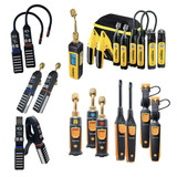 Wireless Probes
-
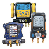 Digital Gauges
-
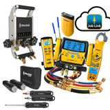 Smart Systems
-
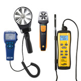 Anemometers
-
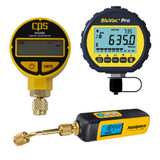 Vacuum Measurement
-
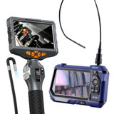 Visual Inspection
-
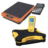 Digital Scales


