



Troubleshooting Low Airflow the Right Way: Localize, Then Verify
Cooling season fills your schedule fast, and a lot of calls trace back to one culprit: low airflow. It shows up as weak cooling and uneven temperatures room to room; and an iced-up evaporator coil when it gets bad enough. Airflow and charge are the only two things you can adjust on a system, and airflow has to be right before you can trust a charge reading.
The difference between a clean fix and a callback usually comes down to one thing: whether you measured or guessed. Here is a repeatable order of operations that finds where the restriction lives. Low airflow often comes down to a restriction somewhere in the air path. The job is to localize where, before touching anything. Keep one distinction in mind as you work. Some methods estimate airflow, which is fine for a quick check. Others measure it, which is what you need when you are proving performance.
1. Set airflow at the appliance first
You cannot charge or judge a system on bad airflow.
Airflow is always set at the appliance, not at the registers. Target a nominal 400 CFM per ton for A/C, 450 CFM per ton for heat pumps, and the middle of the temperature-rise range for furnaces. Always defer to the manufacturer's spec. In a humid climate, dial the A/C side down toward 350 to 375 CFM per ton so the coil pulls more moisture out of the air; you're trading a little sensible capacity for the latent removal the homeowner actually feels. Why it leads: refrigerant readings taken over bad airflow send you chasing a charge problem that does not exist. Get airflow right and everything downstream becomes trustworthy.
2. Measure Total External Static Pressure
Confirm the problem and identify where to look next.
Measure static pressure on the return and supply sides, add the readings together, and compare the total to the equipment's rated maximum external static pressure. Where you put the probes decides what that number includes: the return reading goes between the filter and the blower, the supply reading comes off the plenum right after the coil. Drill them anywhere else and you're comparing your total against a rating it doesn't match. Compare the individual readings to identify whether the restriction is on the return side, the supply side, or both. Use a Fieldpiece SDMN6, Testo 510i, or UEi EM152 with static pressure tips. A wireless probe logs the readings straight into measureQuick instead of onto the back of your hand.
-Taking measurements with the SDMN6
3. Measure pressure drop across components
Locate the restriction: filter, coil, or heat exchanger.
Measure the static pressure drop across each major component: the filter, the evaporator coil, and the furnace heat exchanger if there's one in the cabinet. Large static pressure drops point to a restriction, often caused by dirt. Record these values at commissioning so you have something to compare against later. One caution: a wet coil produces a very different pressure drop than a dry one. Converting coil pressure drop to CFM also requires the manufacturer's performance table. Without it, you're estimating airflow rather than measuring it.
4. Quantify appliance airflow when you need a real number
From estimate to measurement.
When a gut check isn't enough and you need actual CFM at the equipment, you have three routes: a TrueFlow grid dropped into the filter slot, a pitot traverse, or the temperature-rise method on the furnace side.
For the pitot traverse, measure in a straight duct run, 2 to 3 duct diameters downstream of the last fitting (more is better), so turbulence does not corrupt the reading. The temperature-rise route needs two accurate dry-bulb air probes, one in the return and one in the supply, plus the furnace's real output in BTUH (nameplate input times steady-state efficiency). Measure the rise across the furnace, then CFM = output BTUH divided by (1.08 times the temp rise).
Keep the probes out of the heat exchanger's line of sight, or radiant heat skews the reading. A pair of Testo 915i Smart Probes or NAVAC NSH1 psychrometers reads both points into their native apps or MeasureQuick.
5. Check the terminals
Register readings tell you where the air goes, not what the coil sees.
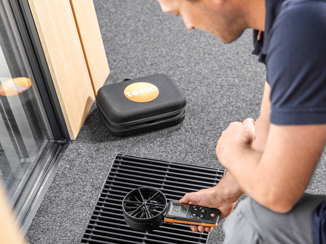
Now move to the grilles with a vane anemometer or a flow hood. Here is the trap: you cannot verify airflow across the coil by reading at the registers, because duct leakage makes the two numbers diverge. Appliance airflow answers "is the equipment moving air?" Terminal airflow answers "where is the air going, and what room is starved?"
A tech who reads a low bedroom register and starts adjusting the blower is treating a distribution problem as an equipment problem. What you're actually after is CFM per register against the room's design number, not a velocity target. Face velocity swings with the grille's free area. Read the velocity, multiply by the free area, and compare that CFM to design. The Testo 417 vane handles supplies and returns; the 405i hot wire suits low velocity.
-The testo 417 Vane Anemometer in action
6. Ducts and design
When the box is fine but the house still will not heat or cool.
Airflow is right at the appliance, the equipment checks out, and the home is still not comfortable. Now evaluate the duct system for leakage, sizing, and design, and consider whether the load calculation was right in the first place, since equipment is often sized without rigorous load math. The Building HVAC Science episode Beyond Manual J (EP255) is a solid next step.
7. Verify the fix
The step that prevents a callback.
After the correction, re-measure total external static and airflow. Confirm the numbers moved into range and log them. This is the step most checklists skip, and it is the one that separates a closed call from a return trip. It is also your paper trail: proof the system left in spec.
Low airflow rewards a consistent process. Run the same order every call: set airflow at the appliance, measure total external static pressure, localize the restriction, measure where you need a real number, separate equipment from distribution, then verify the fix. Measure before you adjust, and measure again after.
To go deeper on airflow verification and connected workflows, listen to Building HVAC Science, EP237 (From Data to Decisions). And if you want to round out your airflow and static kit, browse the tools here: https://trutechtools.com/airflow-measurement-tab-tools/
Publicaciones recientes
-

Stop Feeding Google Bad Leads: Get Digital Advertising To Drive Revenue
A TruTech Tools exclusive article brought to you by: ClickToast Digital Advertising www.cli …13th Sep 2026 -

'Keep HVAC Local' Hat Sales Benefit the GRIT Foundation
WorkHero has launched the Keep HVAC Local campaign to raise money for the GRIT Foundation a …2nd Sep 2026 -
5 Essential HVAC Tools Technicians Reach for Every Day
Every technician has favorite tools, but some get used on nearly every service call. I don’t …16th Aug 2026